
CE-121 ઇંધણ વપરાશ મીટર સ્પષ્ટીકરણો
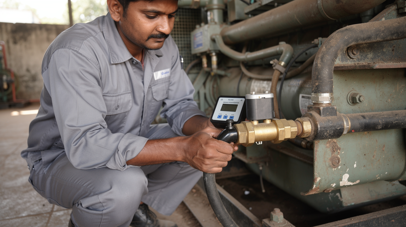
આ CE-121 fuel consumption meter uses separate positive-displacement sensors on diesel supply and return lines to calculate fuel used. Select its 1/4-inch to 1-inch threaded sensor variant to match the actual connection, then check line flows and power supply.
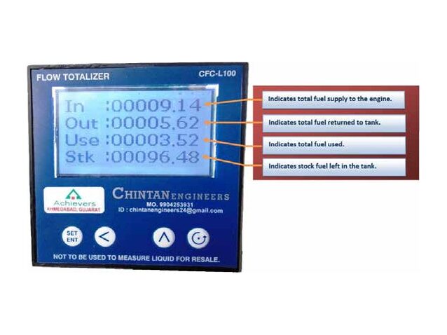
How the CE-121 measures supply, return and used fuel
One CE-121 sensor measures diesel supplied to the engine. A second measures fuel returning from it. The display unit calculates used fuel as the difference between the two readings.
A supply-line reading alone would count diesel that flows back to the tank unused. The backlit display shows in-flow, out-flow, used fuel and stock fuel. This setup suits critical-system fuel monitoring, where every litre supplied and returned needs to be tracked.
CE-121 specifications at a glance
The CE-121 uses anodised aluminium positive-displacement sensors. Its accuracy is ±1% RS or 0.1% FSD in the standard installation position.
| પરિમાણ | CE-121 specification |
|---|---|
| Sensor type | Positive displacement meter |
| Sensor material | Aluminium anodize |
| ચોકસાઈ | ±1% RS or 0.1% FSD (standard installation position) |
| ડિસ્પ્લે | In-flow, out-flow, used fuel and stock fuel; backlit |
| શક્તિ | 220V AC / 12V DC / 24V DC |
| આઉટપુટ | RS-485 Modbus (optional) |
RS means reading; FSD means full-scale deflection. The accuracy line gives two alternative expressions, not a combined tolerance for calculated fuel use.
Each sensor has its pulse-per-litre value marked on its body. Calibration uses pure diesel at three test pressures: 0.5 bar, 4 bar and 25 bar. At each pressure, the calculator records pulse-per-litre at 25%, 50%, 75% and 100% of the sensor’s flow range, which supports accuracy across partial loads as well as full flow.
The display reads four values at once: in-flow, out-flow, used fuel and stock fuel. No separate totalizer or reset function exists beyond these four readings. For broader meter terminology, see the fuel flow meter specification article.
Match the sensor variant to the required thread
The six CE-121 variants cover 1/4-inch through 1-inch threads. Two models share the 1/2-inch connection.
| Sensor model | Thread size |
|---|---|
| CE-121-006 નો પરિચય | 1/4 inch |
| CE-121-008 | 3/8 inch |
| CE-121-012 | 1/2 inch |
| CE-121-015 | 1/2 inch |
| CE-121-020 | ૩/૪ ઇંચ |
| CE-121-025 નો પરિચય | ૧ ઇંચ |
Thread size alone cannot distinguish CE-121-012 from CE-121-015. Specify the required supply and return flow ranges when choosing between them. Engine ratings appear in the installation guidance, but rating alone is not a reliable model-selection rule.
Check the installation before choosing a variant
Check both fuel-line connections, both line flows, sensor space and available power before choosing a thread size.
- Measure the supply and return connections separately; they need not share the same thread.
- Identify each connection’s thread form and pitch, not just its nominal size.
- Record the operating flow range in each line; the return line carries fuel the engine has not used.
- Allow space for two sensor bodies and the display unit.
- Confirm whether the installation supplies 220V AC, 12V DC or 24V DC.
A 1/2-inch pipe connection narrows the choice to CE-121-012 or CE-121-015. It does not settle the flow-range question, so check the required operating flows with the engineering team before selecting either model.
Power and optional communications
The CE-121 accepts three power inputs: 220V AC for fixed installations, 12V DC and 24V DC for vehicle or generator onboard supply. This dual-voltage DC option matters for fleet work, where the vehicle or generator supply may be 12V or 24V depending on the unit.
RS-485 Modbus is an optional output, not a standard fitting. Order the Modbus board with the unit if remote monitoring is needed, since fitting it later means opening the display housing.
With Modbus fitted, the CE-121 can connect to a server for remote data monitoring. This lets a fleet office pull in-flow, out-flow, used fuel and stock fuel figures without visiting each unit. For a plant connection, check the receiving system’s register requirements alongside the PLC/SCADA integration article.
વારંવાર પૂછાતા પ્રશ્નો
What does the CE-121 display? Its backlit display shows in-flow, out-flow, used fuel and stock fuel.
What accuracy is listed for the CE-121? The catalog lists ±1% RS or 0.1% FSD accuracy in the standard installation position.
Does the CE-121 have two fuel sensors? Yes. One sensor measures diesel supplied to the engine and the other measures fuel returning from it; the system calculates the difference as used fuel.
Which CE-121 model has a 1/2-inch thread? Both CE-121-012 and CE-121-015 have 1/2-inch threads. Match the model to the required line flow as well as the connection.
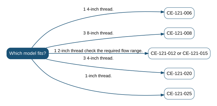
Quick pick
- CE-121-006: 1/4-inch thread.
- CE-121-008: 3/8-inch thread.
- CE-121-012 or CE-121-015: 1/2-inch thread; check the required flow range.
- CE-121-020: 3/4-inch thread.
- CE-121-025: 1-inch thread.
ચોક્કસ ફરજ માટે મીટર અથવા ડિસ્પેન્સરની જરૂર છે?
અમને પ્રવાહી, પ્રવાહ શ્રેણી અને સ્થળ જણાવો; અમે એક કાર્યકારી દિવસની અંદર મોડેલ અને ભાવ સાથે જવાબ આપીશું.