
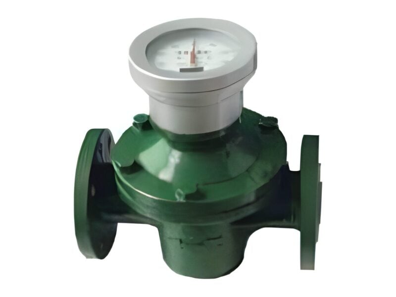
CE-1-80
CE-1-80 Flow Meter
CE-1-80 diesel flow meter with a flow range of 140 L/Min.
- Minimum Flow
- 140 L/Min
- Accuracy
- 0.5 %
- Working Pressure
- 1.0 to 1.5 mpa
Fuel monitoring
Pumps & nozzles
Batching
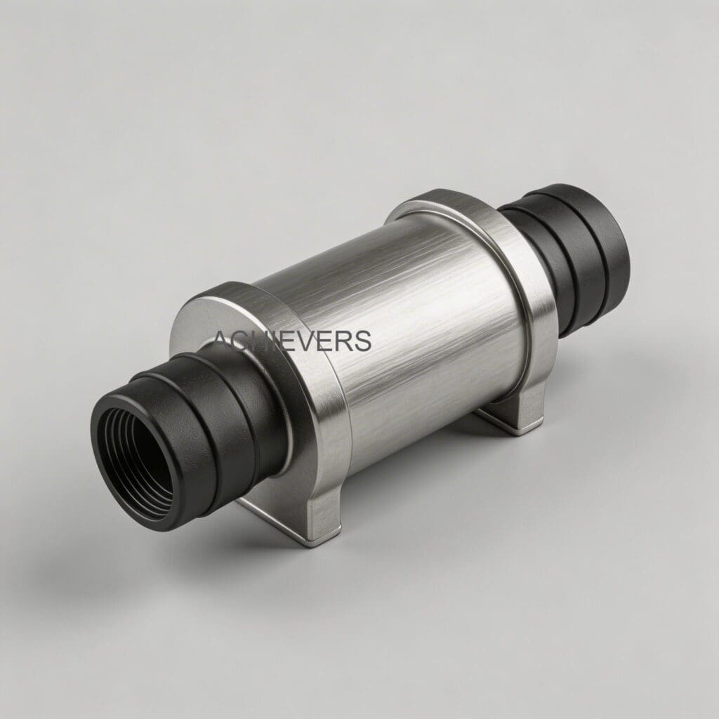
Accurate fluid measurement is the backbone of operational efficiency, inventory reconciliation, and financial accountability in modern industrial facilities. Whether handling diesel, marine gas oil, or heavy lubricants, selecting high-precision equipment is only the first step. The reality of industrial fluid dynamics dictates that physical installation and system integration determine up to 80% of a meter’s long-term performance. A poorly installed meter will suffer from parasitic pressure drops, cavitation, and inaccurate pulse generation, negating the precise engineering of its internal mechanisms.
This comprehensive technical guide serves as a foundational resource for plant managers, instrumentation engineers, and project leads executing global fuel management projects. It details the rigorous engineering practices required to install, integrate, and validate positive displacement, helical, and piston flow meters. By following these protocols, facilities can achieve tight ±0.2% custody-transfer accuracies and ensure compliance with international metrology standards such as ISO, API MPMS, and OIML. Utilizing a high-quality Diesel Flow Meter ensures a solid mechanical baseline, but unlocking its full operational lifespan requires strict adherence to fluid conditioning, mechanical isolation, and electrical signal integrity protocols.
Before physically modifying piping or breaking containment on a fuel transfer line, a stringent site assessment and engineering review must be conducted. This phase verifies that the selected Diesel Flow Meter matches the process envelope and that the surrounding infrastructure will not introduce metrological errors.
Review your process data against the operational limits of the selected meter technology. Positive displacement (PD) meters are inherently immune to flow profile disturbances but are sensitive to particulate matter, whereas helical sensors provide vast viscosity tolerances but require specific calibration curves (K-factors) for changing fluid densities.
| Model | Flow Range | Accuracy | Signal / Display | Highlight Features | Ideal Application Focus |
| :— | :— | :— | :— | :— | :— |
| CE-110 Mechanical PD Meter | 20 – 300 L/min (1"–2" sizes) | ±0.5% | Mechanical counter (reset + cumulative) | Low pressure drop, viscosity-independent | Fuel depots needing rugged, non-electric registers |
| CE-111 Digital PD Meter | 20 – 300 L/min | ±0.5% | LCD totalizer + flow rate | Battery-backed electronics, pulse-ready | Skids requiring local digital readouts |
| CE-113 High Accuracy Transfer Meter | 25 – 1,300 L/min (40–100 mm) | ±0.2% | Register, printer, pulser combinations | Air eliminator, strainer, custody transfer build | Bulk loading gantries, ticket printing |
| CE-210 Helical Flow Sensor | 5 – 10,000 L/h | ±0.5% or ±1% | Pulse, Hall/Reed, LCD, 4–20 mA | Handles viscosities up to 1,000,000 mm²/s | Automation projects, high-viscosity batching |
| CE-212 Piston Flow Meter | 5 – 60 L/min | ±0.2% | Mechanical or pulse output | 4-piston design, rotary valve | Integrated fuel dispensers and preset batching |
Executing a flawless installation requires mechanical precision and electrical discipline. The following procedure represents the industry standard for configuring a Diesel Flow Meter in heavy-duty environments ranging from offshore platforms to high-throughput logistics hubs. Whether dealing with a comprehensive Diesel Flow Meter installation guide or evaluating specific OEM protocols, this sequence guarantees metrological integrity.
Understanding Diesel Flow Meter wiring pulse output and 4-20 mA setup is critical for bridging the gap between mechanical movement and digital automation systems such as PLCs, SCADA, or a centralized Liquid Batching System.
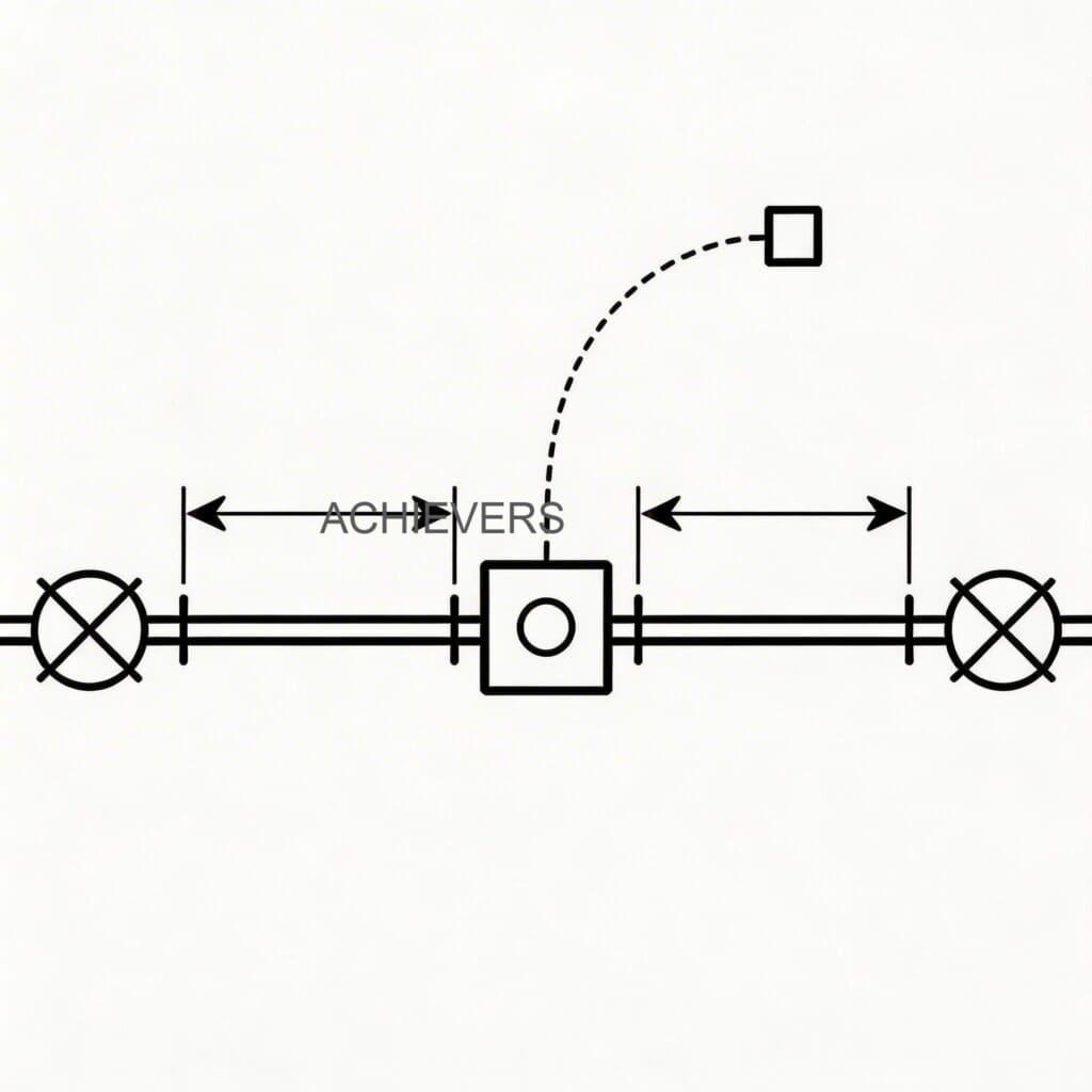
Commissioning translates static installation into dynamic operation. This section serves as a definitive Diesel Flow Meter commissioning checklist for manufacturers, integrators, and site engineers. Improper startup procedures—such as rapidly flooding an empty meter—can cause hydraulic shock (water hammer), snapping rotor shafts and destroying calibration mechanisms.
Even experienced piping contractors can introduce errors when they treat high-precision metrology equipment like standard pipe fittings. Understanding how to install a Diesel Flow Meter in fuel transfer line environments requires recognizing and mitigating these frequent failure points. While executing a Diesel Flow Meter installation in India for industrial fuel monitoring, or deploying systems in the harsh climates of the Middle East and African mining sectors, extreme ambient temperatures and demanding duty cycles require specific consideration.
| Mistake | Why It Happens | Consequence | Correct Approach |
| :— | :— | :— | :— |
| Omitting Upstream Strainers | Trying to save space or reduce piping costs on the skid. | Welding slag and pipe scale enter the precision measuring chamber, scoring rotors and seizing the meter. | Always install a 100-mesh strainer exactly 1 to 2 pipe diameters upstream of the meter inlet. |
| Bypassing Air Eliminators | Assuming the fuel supply is "clean and solid" from the storage tank. | Cavitation and tank aeration cause the meter to measure air volume as liquid, creating severe fuel reconciliation losses. | Install an API-compliant air eliminator vessel at the highest pipeline elevation before the meter. |
| Vertical Rotor Orientation | Mounting the meter sideways to fit into tight dispenser cabinets or gantries. | Gravity pulls the rotors against the lower thrust bearings, causing rapid asymmetric wear and loss of ±0.5% accuracy. | Flanges may be vertical or horizontal, but the internal measuring element shafts must be strictly horizontal. |
| Double-Grounded Shields | Electrical contractors connect the cable shield wire at both the flow meter and the PLC cabinet. | Creates an antenna for plant EMI/RFI, inducing phantom pulses that artificially inflate fuel totals. | Terminate and ground the drain wire/shield only at the receiving PLC or control cabinet earth bar. |
| Piping Strain on Housing | Failing to install load-bearing pipe supports; bolting misaligned flanges directly to the meter. | The mechanical stress warps the meter casing. The internal rotors bind against the walls, halting fluid flow completely. | Align pipes perfectly. Use structural pipe supports on both sides. The meter should bear zero external structural weight. |
| Fast Valve Actuation | Using quick-acting pneumatic butterfly or ball valves downstream without damping. | Sudden opening/closing causes immense hydraulic shock (water hammer) that shatters internal gears and seals. | Use multi-stage control valves or slow-opening actuators (minimum 5-second stroke time) to manage fluid momentum. |
A proactive maintenance strategy prevents unexpected downtime and preserves the metrological traceability established during commissioning. Heavy commercial users searching for a reliable Diesel Flow Meter supplier for industrial B2B buyers must prioritize long-term serviceability and spare part availability as highly as initial capital cost.
Establish the following preventive maintenance lifecycle to ensure continuous ±0.2% to ±0.5% accuracy across millions of liters of throughput.
| Maintenance Task | Frequency | Technical Notes |
| :— | :— | :— |
| Strainer Basket Cleaning | 1st Week, then Monthly | Check differential pressure across the strainer. High DP indicates a clogged basket, which leads to fluid starvation and cavitation. |
| Visual Leak and Seal Inspection | Weekly | Inspect flange gaskets, mechanical register base, and packing glands for hydrocarbon weeping. Address immediately to prevent vapor hazards. |
| Proving and Calibration Check | Every 6 to 12 Months | Use a certified prover to verify accuracy. High-wear environments (handling unrefined oils) may require quarterly recalibration to adjust the K-factor. |
| Air Eliminator Float Check | Semi-Annually | Open the air eliminator head. Clean the float mechanism and inspect the reed valve seat. Ensure the atmospheric vent line is unobstructed. |
| Register Gearing Lubrication | Annually | For mechanical registers (CE-110, CE-113), inspect the gear train. Apply manufacturer-specified non-gumming light machine oil. |
| Bearing and Vane Inspection | 3 to 5 Years (Duty dependent) | Perform a planned teardown. Measure clearances of rotors/pistons against factory specs. Replace journal bearings and O-rings. |
Recommended On-Site Spare Parts Inventory:
To prevent catastrophic downtime during bulk loading operations, site managers should maintain a minimum critical spares inventory, including:
Q: Can these positive displacement flow meters handle high-viscosity fluids or biofuels?
A: Yes. Positive displacement models like the CE-110 and CE-113 naturally handle varying viscosities, actually improving volumetric efficiency at higher thicknesses (up to 5,000+ mPa·s). The CE-210 helical model is specifically engineered for extreme viscosities up to 1,000,000 mm²/s. Always specify the fluid type during procurement so the correct internal seal materials (e.g., Viton, Kalrez) can be fitted.
Q: How do we integrate the meter's pulse output with our existing automation system?
A: The CE-111 and CE-210 models provide industrial-standard open-collector (NPN/PNP) or Hall Effect pulse outputs. These are easily integrated into any standard PLC, SCADA remote terminal unit, or specialized preset batch controller. Ensure your control system applies the correct K-factor (Pulses/Litre) provided on the meter’s calibration certificate.
Q: What is the mandatory straight pipe run required before the meter?
A: Unlike turbine or ultrasonic meters, positive displacement meters (CE-110, CE-111, CE-113, CE-212) isolate exact fluid volumes mechanically, making them highly immune to turbulent flow profiles. However, standard engineering best practice dictates a minimum of 5 pipe diameters upstream and 3 diameters downstream to minimize localized pressure drops and ensure smooth fluid delivery.
Q: Why does the meter continue to count pulses when no fluid is actively being pumped?
A: This usually indicates severe electrical noise (EMI/RFI) interfering with the pulse transmission line. It is almost always caused by improper shielding, routing low-voltage signal cables alongside high-voltage VFD power lines, or grounding the cable shield at both ends. Rewire the signal cable with proper isolation and single-point grounding.
Q: Is it necessary to install an air eliminator for every application?
A: If the fluid is supplied via gravity, or if the source tank is completely stable and the pipe remains flooded at positive pressure, an air eliminator may be bypassed. However, for applications involving truck unloading, long suction lifts, or custody transfer (where air would be metered as payable liquid), an API-compliant air eliminator is absolutely mandatory to ensure billing accuracy.
Q: How often must we execute physical metrological proving?
A: Baseline calibration should occur immediately upon commissioning. Thereafter, standard commercial operations verify accuracy annually. For strict custody transfer operations, high-throughput gantries, or applications bound by legal metrology frameworks, proving must be executed quarterly or every 1,000,000 liters, using a thermally corrected master prover.
Q: Can this metering technology be deployed in explosive ATEX environments?
A: Yes. For hazardous areas, specify the environment (e.g., Zone 1 or Zone 2) during engineering. The meters can be equipped with Ex d (flameproof) or Ex i (intrinsically safe) electrical enclosures, ATEX-certified cable glands, and mechanical registers that require zero electrical power, rendering them inherently safe for highly explosive atmospheres.
To ensure your facility achieves exact fuel reconciliation and long-term mechanical reliability, our engineering team is available to review your P&ID and process requirements. Contact us today with your specific fluid type, flow rate envelope, operating temperatures, and automation requirements to receive a customized specification review and configuration guide.
CE-1-80 diesel flow meter with a flow range of 140 L/Min.
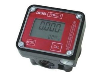
CE-102 diesel flow meter with a flow range of 7-40 LPM.
Tell us the fluid, flow range and site; we reply with a model and a quote within one working day.