


A 1% calibration drift on a 5,000 L/day throughput costs your operation exactly ₹1.35 lakh per month in untracked diesel waste. In my 22 years engineering and calibrating over 5,000 flow measurement systems—from major ONGC refinery pipelines down to private fleet depots in rural Gujarat—I have watched countless plant engineers chase "ghost" consumption anomalies. When managers call me, they almost always suspect fuel theft. But nine times out of ten, the culprit is a degrading mechanical chamber, electromagnetic interference on a signal line, or undiagnosed air entrainment.
Industrial flow measurement is unforgiving. When you push hydrocarbons through precision-machined geometries, you are fighting a continuous battle against particulate abrasion, fluid viscosity shifts, and environmental electrical noise. If you are tasked with industrial flow meter maintenance, swapping out hardware blindly is a fast way to blow your OPEX budget. You need to diagnose the physics of the failure.
Here is the field-tested approach to diagnosing and eliminating flow meter calibration drift, turbine signal loss, and parasitic pressure drops in your plant.
In This Article
- Diagnosing Flow Meter Calibration Drift in PD Systems
- Solving Turbine Flow Meter Signal Loss and Electrical Noise
- Air Entrainment: The Silent Accuracy Killer
- TCO Analysis and Specification Matrix
- Troubleshooting Pressure Drops Across the Meter
- Frequently Asked Questions
- Final Recommendations from the Field
Diagnosing Flow Meter Calibration Drift in PD Systems
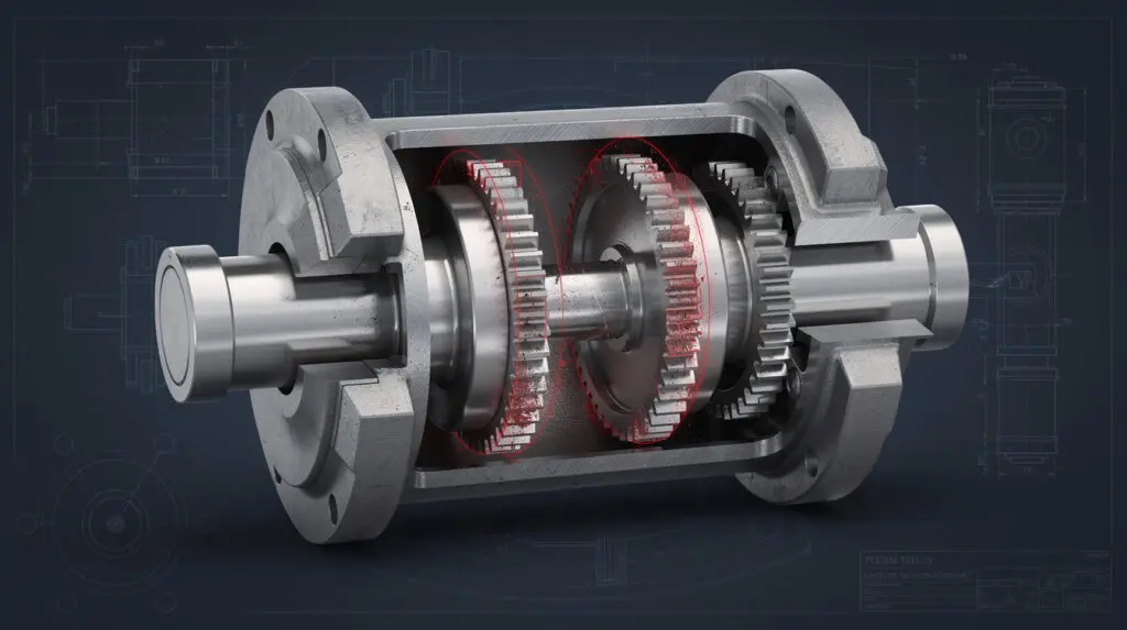
Positive Displacement (PD) meters, such as oval gear or piston types, are the gold standard for high-viscosity hydrocarbon measurement. They operate by trapping a fixed volume of fluid between machined rotors and the outer casing. Because they measure discrete volumes, their baseline accuracy is exceptional. However, this tight mechanical clearance is exactly where calibration drift originates.
When a PD meter starts under-registering or over-registering, the root cause almost always boils down to one of three factors:
1. Mechanical Slip Due to Rotor Wear
If your fuel carries suspended rust or dirt—a harsh reality in poorly sumped bulk storage tanks—these particulates act as an abrasive slurry. Over millions of cycles, the abrasive action wears down the tips of the oval gears or the walls of the measuring chamber.
As clearances widen, fluid bypasses the measuring chamber without turning the rotors. This phenomenon is called "slip." Ever wonder where that missing 100 liters went? It slipped right past your rotors, meaning the meter will under-register the volume passing through it. (I've calibrated enough heavily worn meters to know they don't belong anywhere near unfiltered fuels—which is exactly why you never install a PD meter without an upstream Y-strainer).
2. Viscosity Variations and Temperature Swings
Fuel viscosity changes with temperature. A diesel line running at 40°C during a hot summer afternoon in Ahmedabad behaves very differently than the same line at 15°C during winter. As viscosity drops and the fluid gets thinner, the slip factor naturally increases. If your meter was proved and calibrated for thick winter fuel, it will drift out of tolerance in the summer heat.
3. Bearing and Shaft Drag
In my experience, if the meter is under-registering significantly at low flow rates, the bearings supporting the rotors are likely failing. Increased mechanical friction means it takes more fluid pressure just to initiate rotation. You'll notice massive calibration drift at the lower end of your flow range, while your high-flow accuracy remains deceptively stable.
Pro Tip: Proving your meter against BIS Standards
To verify drift, run a volumetric test using a Legal Metrology-stamped prover can (IS 14883 compliant). Test at 20%, 50%, and 100% of your maximum flow rate. If the error curve is non-linear across these flow rates, your internal chamber is worn out. If the error is linear (e.g., exactly -0.8% across all flows), the hardware is sound, and you simply need to adjust the mechanical calibration wheel or digital K-factor.
Losing diesel to mechanical wear and calibration drift?
Upgrade to a custody-transfer class positive displacement meter with ±0.2% accuracy and robust internal metallurgy.
Solving Turbine Flow Meter Signal Loss and Electrical Noise
Turbine meters are a completely different beast. A bladed rotor spins in the flow stream, and a magnetic pickup coil generates an electrical pulse each time a blade passes. Turbine flow meter signal loss is one of the most frustrating electrical issues plant engineers face, largely because the mechanical hardware is often perfectly intact.
When your PLC or batch controller starts showing zero flow while the pump is running, or gives you erratic spikes in flow rate, check the following:
Sensor Gap and Magnetic Degradation
The Hall-effect or variable reluctance sensor sits in a blind bore above the rotor. If heavy pipe vibration backs the sensor away from the rotor by even a millimeter, the magnetic field interaction weakens. The resulting millivolt pulse drops below the trigger threshold of your pre-amplifier. Additionally, if you are operating near the 80°C limit of the system, the permanent magnet inside the pickup can physically degrade. It happens more often than you'd think.
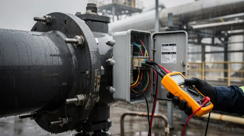
Electromagnetic Interference (EMI) in the Cable Run
If I had a rupee for every time a VFD caused phantom flow readings, I'd have retired by now. In crowded industrial estates like GIDC, power quality is notoriously dirty. If the unamplified pulse signal from your turbine meter runs in the same cable tray as the power lines for a 50 HP Variable Frequency Drive (VFD), the VFD's switching frequencies will induce massive noise on the flow signal line. Your batch controller interprets this electrical noise as flow pulses, causing drastic over-registration.
Monsoon Humidity and Ground Loops
Indian monsoons are brutal on field instruments. Moisture ingress into the terminal box of a turbine meter creates parasitic paths to ground. A ground loop occurs when the meter body and the receiving PLC are grounded at different voltage potentials. This difference drives a circulating current through the signal shield, completely distorting 4-20mA signals or destroying pulse integrity.
Warning: Cable Shielding Protocol
Never ground the shield of a flow meter signal cable at both ends. Always ground the shield only at the receiving end (the PLC or totalizer panel). Grounding both ends creates a classic ground loop antenna that will ruin your ±0.5% accuracy.
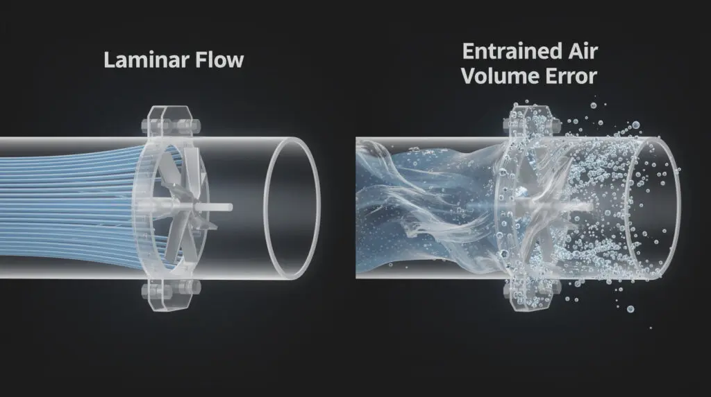
Air Entrainment: The Silent Accuracy Killer
No flow meter on earth can distinguish between a liter of liquid and a liter of air. If your transfer pump is sucking in air through a degraded suction seal, or if you completely empty a bulk tank, that entrained air passes right through the meter.
In high-accuracy positive displacement meters—like our CE-113 Transfer Meter—air entrainment spins the rotors aggressively. Because air has near-zero viscosity, it offers no mechanical resistance. I have seen air blasts over-speed a PD meter so severely that it sheared the internal timing gears clean off. More commonly, though, you simply pay for "ghost" fuel. I once evaluated a site where 5% of their monthly "fuel" bill was just atmospheric air. It is mathematically unavoidable unless mitigated.
To troubleshoot and prevent this:
- Install an Air Eliminator: Custody-transfer setups, specifically those complying with OIML R117, mandate an air eliminator tank installed immediately upstream of the meter. This tank slows the fluid velocity, allowing air bubbles to rise and vent via a float valve before the fluid reaches the measuring chamber.
- Check Net Positive Suction Head (NPSH): If the pressure drop on the suction side of your pump is too high, the diesel will locally vaporize (cavitation). These vapor bubbles pass through the meter, artificially inflating the volume, before collapsing back into liquid further down the line.
If you want the exact piping layouts to avoid this, review our Fuel Flow Meter Installation: Engineer's Setup Guide.
TCO Analysis and Specification Matrix
Sometimes, troubleshooting yields a terminal diagnosis—meaning the meter is just damaged beyond repair. At this stage, specification becomes critical. Procurement teams often look at the initial capital cost, ignoring the Total Cost of Ownership (TCO) over a 5-year lifecycle.
Look at the actual numbers. If a cheap, non-industrial flow meter drifts by 1% on a 5,000 L/day diesel line, you lose ₹1.35 lakh monthly. Upgrading to a heavy-duty CE-113 with ±0.2% accuracy caps that uncertainty, paying for itself within the first 14 days of operation.
Here is a technical comparison of how Chintan Engineers' standard models handle different field scenarios based on our deployment data:
| Model | Measurement Technology | Flow Range | Accuracy | TCO / Troubleshooting Profile |
| :— | :— | :— | :— | :— |
| CE-110 | Mechanical Oval Gear PD | 20 – 300 L/min | ±0.5% | Rugged, viscosity-independent. Immune to signal loss (mechanical counter). Requires upstream strainers to prevent gear wear. |
| CE-210 | Turbine / Helical Sensor | 5 – 10,000 L/h | ±0.5% | Exceptional for low-viscosity fuels. Requires strict adherence to grounding protocols to avoid signal loss. Tolerates pressure pulsations. |
| CE-113 | Custody Transfer PD | 25 – 1300 L/min | ±0.2% | My go-to for strict accountability. Aluminium body with Viton seals. Handles up to 10 BAR at 80°C. Virtually eliminates drift when properly maintained. |
| CE-212 | Micro-piston PD | 5 – 60 L/min | ±0.2% | Micro-accurate. Ideal for high-precision diesel dispensing and engine consumption monitoring. External calibration wheel simplifies drift correction. |
Selecting the right meter configuration limits failure modes before the pipe is even pressurized. Unsure which technology matches your fluid viscosity profiles? Refer to our guide on Decoding Oil Flow Meter Specs: An Engineer's Guide.
Did You Know: The Importance of Calibration Sealing
Under the Indian Legal Metrology Act, any flow meter used for custody transfer (buying or selling fuel) must feature wire-and-lead seals on the calibration adjustment mechanism. Breaking this seal to fix a calibration drift without an inspector present is a severe compliance violation. Models like the CE-113 are specifically cast with sealing lugs for this exact purpose.
Troubleshooting Pressure Drops Across the Meter
Every flow meter consumes energy from the pipeline to operate. We record this as a pressure drop (ΔP).
If your plant operators complain that the diesel transfer pump is suddenly struggling to deliver the required flow rate, do not immediately blame the pump. Check the pressure drop across the flow meter. A sudden increase in ΔP indicates a severe restriction.
- Clogged Upstream Strainer: The Y-strainer is designed to sacrifice itself to protect the meter. A clogged strainer basket will cause massive pressure drops and starve the pump. I've pulled baskets out of diesel lines that looked like they were filtering mud. Pull the basket, clean the 60-mesh screen, and re-install.
- Frozen or Seized Rotors: In a PD meter, if a hard particulate jams between the rotor and the casing, the rotors will stop turning. The meter effectively becomes a plugged pipe. You will read zero flow, and the pressure upstream of the meter will rapidly spike to the pump's deadhead pressure. Bypass the meter to restore flow, then isolate and rebuild the measuring chamber.
- Viscosity Spikes: Digital meters like our CE-105 and CE-106 handle diesel perfectly. However, if the line is mistakenly used for high-viscosity furnace oil or gear lube without heat tracing, the thick fluid will struggle to pass through the tight internal clearances, resulting in a severe pressure drop.
Need a flow meter built for harsh Indian industrial conditions?
Chintan Engineers manufactures turbine and PD meters tested up to 10 BAR and 80°C, capable of handling rapid viscosity swings.
Frequently Asked Questions
How often should industrial flow meter maintenance be performed?
For diesel dispensing in heavily trafficked depots, clean the upstream strainer basket monthly. Perform a volumetric proving run (calibration check) every 6 months using a certified prover can. Expect to rebuild the internal measuring chamber every 3 to 5 years depending on your total throughput.
What causes a digital fuel flow meter to show flow when the pump is off?
This is classic electromagnetic interference (EMI) or pipe vibration. High-frequency vibration from a nearby motor can "rattle" the turbine rotor just enough to trigger the magnetic pickup. Alternatively, electrical noise from VFDs is bleeding into your pulse cable. Ensure you use twisted-pair shielded cable and ground the shield only at the PLC end.
Can I fix flow meter calibration drift through software?
Yes, but with caveats. If you have a CE-111 Digital Flow Meter and notice a consistent, linear 1% under-registration, you can alter the digital K-factor (pulses per liter) to correct it. However, if the drift is non-linear across different flow rates, software cannot fix it—you have mechanical wear and must replace the internal rotors.
Why did my flow meter accuracy degrade after installing a larger pump?
You likely pushed the meter past its maximum rated flow rate, or the increased suction draw caused the pump to cavitate, introducing air into the line. For example, pushing 400 L/min through a CE-110 (which is rated for 300 L/min maximum) will cause severe slip, excess pressure drop, and rapid mechanical failure.
Do Chintan Engineers' meters handle biodiesel blends?
Yes. Biodiesel (B20 or B100) has different solvency and viscosity characteristics than pure high-speed diesel (HSD). For biodiesel, specify our meters equipped with Viton seals instead of standard Buna-N, as biodiesel can swell and degrade certain standard elastomers over time.
Final Recommendations from the Field
Based on 22 years of field data, throwing away a flow meter just because of a signal loss or a 1% drift is lazy engineering. Diagnosing the actual physics—whether it's abrasive wear in a PD chamber, ground loops destroying a 4-20mA signal, or air entrainment inflating your volume—will save your plant immense capital.
For general diesel transfer where PLC integration is necessary, the CE-210 Turbine Meter provides excellent reliability, provided your electrical shielding is sound. But if you are holding individuals accountable for expensive diesel stocks, or transferring fuel for commercial billing, you cannot compromise on mechanics. My go-to recommendation is the CE-113 High Accuracy Diesel Flow Meter. With its ±0.2% custody-transfer accuracy, heavy-duty aluminium construction, and built-in calibration wheel, it systematically eliminates the ambiguities of fluid measurement.
Stop guessing your fuel consumption numbers.
Secure your diesel lines with flow measurement systems engineered, tested, and calibrated in India for the toughest industrial realities.
