


For industries managing fleet logistics, heavy machinery, or generator power backup, diesel acts as liquid currency. In the Indian industrial landscape, where fuel prices fluctuate and operational margins are tight, even a 1% error in measurement can translate to lakhs of rupees in annual losses. This is why maintaining the accuracy of your Fuel Flow Meter is not just a maintenance task—it is a financial necessity.
However, simply installing a high-quality meter is not the end of the road. Over time, factors such as mechanical wear, viscosity changes due to temperature, and installation variances can cause "drift"—a gradual shift in measurement accuracy. For plant managers and maintenance engineers, understanding the science of calibration, proving, and K-factor adjustment is critical to ensuring that every litre paid for is a litre used.
This guide details the technical process of verifying and calibrating your Fuel Flow Meter, providing a standard operating procedure (SOP) tailored for Indian maintenance teams to reduce billing disputes and operational wastage.
1. What This Product Does: Precision in Fluid Handling
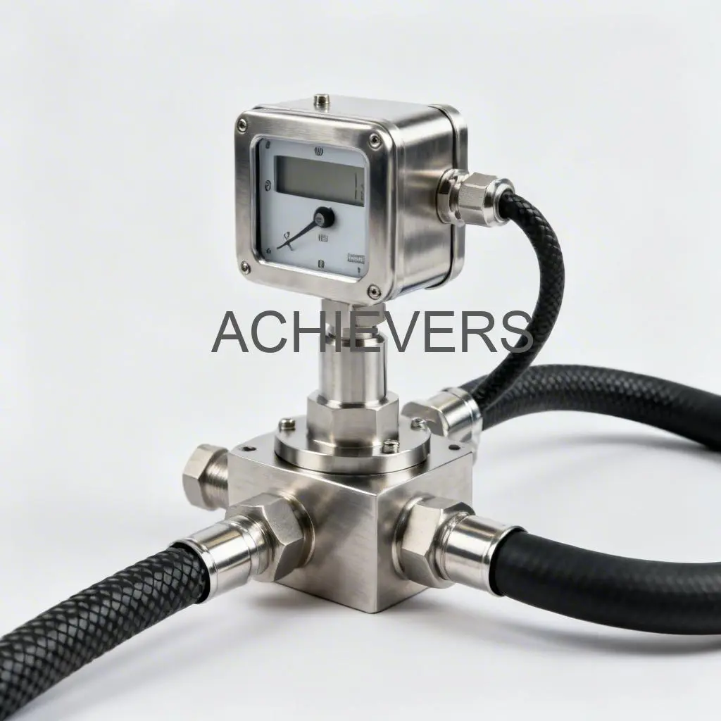
The Fuel Flow Meter is a specialized instrument engineered to measure the volumetric flow of diesel and other hydrocarbon fluids with high precision. Unlike general-purpose water meters, these devices are constructed to handle the specific viscosity, lubricity, and chemical properties of diesel fuel.
At its core, the meter utilizes positive displacement (PD) or turbine technology to capture flow data. In a positive displacement design, the fluid moves through a chamber containing gears or oval rotors. Each rotation represents a specific volume of fluid. Because the machining tolerances are extremely tight, very little fluid slips past the measuring element, ensuring high accuracy even at lower flow rates.
Key Technical Specifications & Features:
- Flow Range Versatility: Designed to handle varying flow rates suitable for both gravity-feed tanks and pump-driven dispensing systems.
- Robust Construction: Built with durable materials (typically cast aluminium or stainless steel bodies) to withstand the harsh environmental conditions often found in Indian mining, construction, and logistics sites.
- Readout Options: Available with mechanical registers (ideal for remote sites with no power) or digital displays offering pulse outputs for remote monitoring.
- Accuracy Standards: engineered to deliver measuring accuracy typically within ±0.5% to ±1% when properly calibrated.
- Pressure Handling: Rated to withstand the line pressures generated by transfer pumps and loading gantries.
2. Practical Calibration Methods: Proving, K-Factors, and Drift Control
Calibration is the comparison of the meter’s reading against a known standard. In the context of diesel transfer, this usually means comparing the meter to a "Proving Can" (a certified volumetric test measure). If the meter reads 100 litres, but the can only holds 98 litres, your meter is under-reading, giving away fuel for free. Conversely, if the can holds 102 litres, you are short-changing the recipient.
Here is a detailed breakdown of how to manage this process, focusing on how to calibrate a fuel flow meter for diesel transfer effectively.
The Diesel Fuel Flow Meter Proving Can Procedure
The most reliable method for field calibration is the volumetric proving method. This should be performed during commissioning and subsequently every 6 to 12 months, or whenever accuracy drift is suspected.
- Preparation: Ensure the system is primed. Run the pump for a few minutes to remove any air pockets from the line. Air passing through the meter will spin the rotors and register as flow, leading to massive inaccuracies.
- Select the Standard: Use a certified proving can (typically 10L, 20L, or 50L capacity) that has been verified by the Weights and Measures department or a NABL-accredited lab.
- The Wet Run: Fill the proving can once to wet the internal surfaces, then drain it completely. This ensures the "wetted surface" retention doesn't skew the test.
- The Test Run: Reset the Fuel Flow Meter to zero. Dispense diesel into the proving can exactly up to the calibrated neck mark.
- Comparison: Check the meter reading.
- Example: Proving Can = 20.00 Litres. Meter Reading = 20.20 Litres.
- Calculation: (Meter Reading – Actual Volume) / Actual Volume × 100 = % Error.
- In this case: (20.20 – 20.00) / 20.00 = +1.0% Error (Over-reading).
Fuel Flow Meter K Factor Setting for Pulse Output
For digital flow meters, calibration is managed via the "K-Factor." The K-Factor represents the number of electrical pulses the meter generates per unit of volume (e.g., 45 pulses = 1 litre).
If your proving run shows an error, you must adjust the K-Factor in the flow computer or display unit.
- The Formula:
$$ \text{New K-Factor} = \text{Old K-Factor} \times \left( \frac{\text{Meter Reading}}{\text{Actual Volume}} \right) $$
Using the previous example where the meter read 20.20L but the actual was 20.00L:
- If Old K-Factor was 100.
- New K-Factor = 100 × (20.20 / 20.00) = 101.
By increasing the K-Factor to 101, you are telling the computer it takes more pulses to count as one litre, effectively slowing down the count to match reality.
Troubleshooting Fuel Flow Meter Accuracy Drift
Drift is rarely the fault of the meter mechanics alone; it is often systemic. If you calibrate today and find the meter inaccurate next week, look for these culprits:
- Air Entrainment: This is the #1 enemy. If the suction line has a leak or the tank level is low, air mixes with diesel. The meter measures the air as fuel. Solution: Install an air eliminator upstream.
- Viscosity Changes: Diesel expands with heat. A meter calibrated at 20°C in the morning might read differently at 40°C in the afternoon. Solution: Use temperature-compensated meters or perform calibration at the site's average operating temperature.
- Wear and Tear: Gritty contaminants in Indian diesel can wear down oval gears, increasing the "slip" (fluid passing without turning the gears). Solution: Always install a strainer (mesh filter) before the meter.
Industrial Diesel Fuel Flow Meter Calibration Checklist (SOP)
To maintain consistency, maintenance teams should follow this simple site-ready SOP:
- Pre-Check: Clean the inlet strainer/filter.
- System Check: Inspect flanges and pipe joints for suction leaks (air ingress).
- Zero Check: Ensure the mechanical counter or digital display resets cleanly to zero.
- Flow Rate Verification: Ensure the pump is delivering flow within the meter’s specified range (e.g., don't run a 100 LPM meter at 5 LPM).
- Repeatability Test: Run the proving test 3 times. If the results vary wildly (e.g., 20.1, 19.8, 20.5), the meter mechanism is likely damaged or air is present. If results are consistent (e.g., 20.2, 20.2, 20.2), the meter is healthy but needs K-factor adjustment.
- Seal: Once calibrated, apply a lead seal or password lock to prevent tampering.
3. Selection and Configuration Guide
Choosing the correct metering solution prevents premature failure and accuracy issues. When sourcing from fuel flow meter suppliers in India, buyers should evaluate the following parameters to ensure the unit matches the application.
1. Flow Rate and Line Size
- Do not oversize: Selecting a 2-inch meter for a low-flow application (like a small generator feed) results in "slippage," where fuel flows past the gears without registering.
- Do not undersize: Pushing high flow through a small meter creates excessive pressure drop and wears out bearings rapidly.
- Guideline: Select a meter where your normal operating flow rate falls in the middle 60% of the meter’s specified range.
2. Material and Fluid Compatibility
- Diesel/Kerosene: Aluminium or Cast Iron bodies are standard and cost-effective.
- Bio-Diesel/Chemicals: Stainless steel (SS316) may be required depending on the corrosive nature of the additives.
- Seals: Ensure Viton or Buna-N seals are used for diesel compatibility to prevent leaks.
3. Display and Output Requirements
- Mechanical: Best for mobile bowsers, mining sites, or areas without reliable electricity. They are "set and forget."
- Digital/Pulse: Essential if you need to connect the meter to a Fuel Management System (FMS), PLC, or remote totalizer. Ensure you specify the required voltage (12V/24V DC or 230V AC).
4. Typical Applications
The versatility of the Fuel Flow Meter allows it to serve various sectors across the Indian industrial landscape.
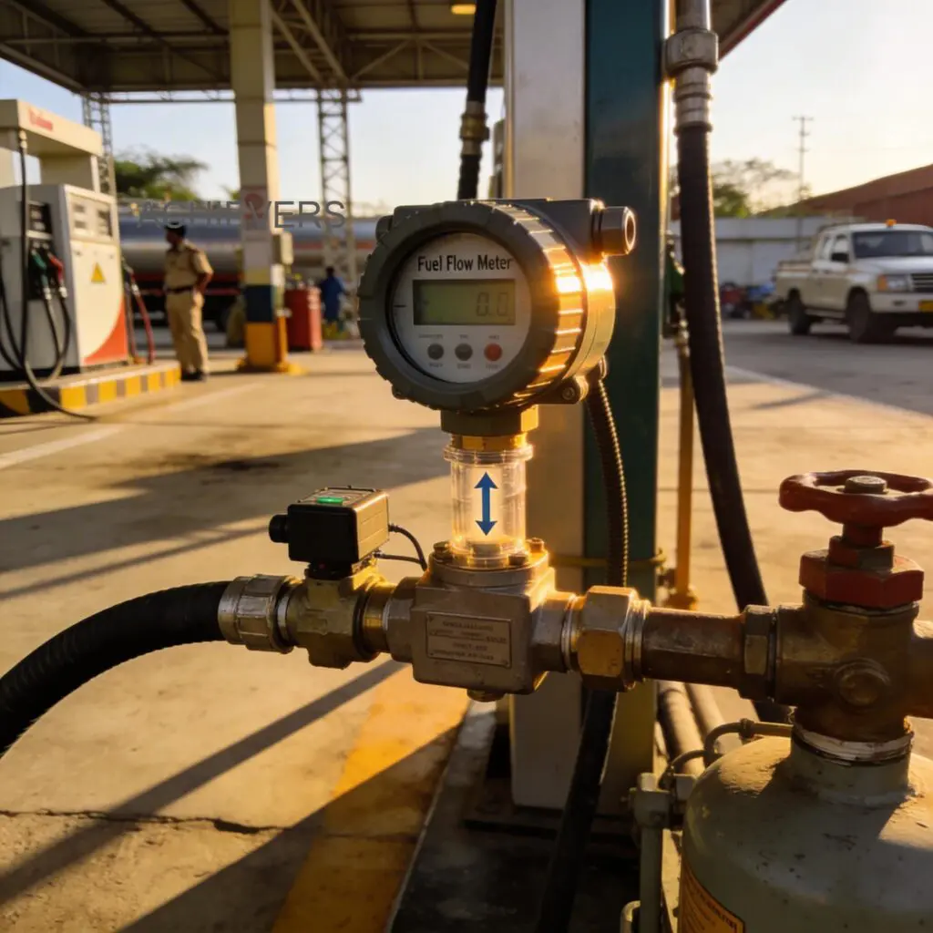
- Fleet Refueling & Transport: Installed on dispensing pumps at logistics hubs to monitor diesel usage for trucks and buses. This helps identifying pilferage and calculating Km/L efficiency.
- Mobile Bowsers: Used on tanker trucks that deliver fuel to remote construction sites or telecom towers. Mechanical counters are preferred here for their ruggedness.
- Generator (DG Set) Monitoring: Installed on the fuel feed line of large diesel generators. This monitors consumption rates (Litres/Hour) to verify engine efficiency and detect fuel theft during power cuts.
- Industrial Batching: Used in chemical or manufacturing plants where specific volumes of diesel or solvents need to be dispensed into mixing tanks for production processes.
- Unloading Gantries: High-capacity meters used when unloading fuel from tankers into underground storage tanks to verify the delivery volume against the bill of lading.
5. Service, Installation, and Support
Even the most robust engineering requires proper installation to deliver certified accuracy.
Installation Best Practices:
- Strainers are Mandatory: Indian industrial environments often involve dust and particulate matter. Installing a Y-strainer or basket filter immediately upstream of the meter is non-negotiable to prevent jamming.
- Mounting Orientation: While many PD meters can be mounted vertically or horizontally, the rotor shafts should typically remain in a horizontal plane to reduce bearing wear. Always follow the specific flow direction arrow cast into the body.
- Vibration Isolation: Do not install the meter directly onto a vibrating pump engine without flexible coupling, as high-frequency vibration can damage digital electronics or mechanical registers.
The Importance of Local Support:
Reliance on imported, "black box" meters can be risky if spare parts are unavailable. Choosing a reputable manufacturer ensures access to calibration services, AMC (Annual Maintenance Contracts), and readily available spares like gears, seals, and counter assemblies. Regular preventative maintenance, including seal replacement and gear inspection, extends the lifecycle of the unit significantly.
Getting the Right Configuration
To ensure your fuel management system delivers precise data and withstands site conditions, selecting the right meter configuration is vital.
Contact our engineering team to specify the correct model for your site.
Please have the following details ready when you reach out:
- Fluid Name: (e.g., High-Speed Diesel, LDO, Kerosene)
- Flow Rate: (Min and Max in LPM or $m^3/hr$)
- Line Size: (e.g., 1 inch, 2 inch)
- Operating Pressure: (Bar / PSI)
- Display Preference: (Mechanical Counter or Digital with Pulse Output)
Our technical experts will help you select the ideal solution to minimize drift and maximize operational efficiency.
