


Accurate fluid measurement is the cornerstone of efficient industrial operations, dictating everything from combustion efficiency in power generation to precise chemical blending and custody transfer. For plant managers and industrial engineers, understanding the complex fluid dynamics and mechanical engineering behind Oil Flow Meters is essential for making informed procurement, installation, and maintenance decisions. Unlike simple velocity-based metering systems, positive displacement technologies offer unparalleled precision, especially when dealing with varying viscosities, fluctuating pressures, and harsh operational environments.
In demanding global sectors such as offshore oil and gas, heavy manufacturing, and automated fluid logistics, standard velocity meters often fail to maintain linear accuracy profiles due to changing Reynolds numbers. By contrast, engineered Oil Flow Meters utilize discrete volumetric trapping to measure fluid mass independent of downstream flow profiles. This technical deep-dive explores the exact mechanics, internal chamber geometry, electronic transduction, and performance variables that define industrial metering. By examining how internal gear clearances and slippage parameters interact with fluid viscosity and temperature, engineering and procurement teams can properly evaluate specifications, accurately calculate pressure drops, and ensure long-term metering stability for global industrial applications.
In This Article
1. Working Principle: How Oil Flow Meters Operates
The positive displacement oval gear oil flow meter working principle relies on the continuous, precise trapping and displacement of fluid volumes. At the heart of the meter lies a precisely machined measuring chamber containing two synchronized, oval-shaped toothed gears. These gears operate on fixed parallel axes and mesh seamlessly at 90-degree offsets.
When a fluid enters the inlet port, it creates a minute differential pressure ($\Delta P$) across the measuring chamber. This pressure gradient exerts a continuous rotational torque on the gears. Because of the specific oval geometry, the fluid pressure acts on the exposed surface area of the primary gear, causing it to rotate and drive the secondary meshed gear. During each full rotation, a specific, unalterable volume of liquid is trapped in the crescent-shaped cavity formed between the outer curve of the gear and the inner wall of the measuring chamber.
For every 360-degree rotation of the gear assembly, the flow meter displaces four distinct "pockets" of fluid. The fundamental equation governing this volumetric flow is:
$Q = V_s \times N \times \eta_v$
Where:
- $Q$ = Volumetric flow rate
- $V_s$ = Swept volume per revolution (a fixed geometric constant)
- $N$ = Rotational frequency of the gears
- $\eta_v$ = Volumetric efficiency (accounting for minute fluid slip)
As the gears rotate, they do not require external power; the kinetic energy of the fluid stream itself drives the mechanical system. This creates a highly stable, self-regulating measurement mechanism that requires no straight-run piping upstream or downstream, unlike turbine or ultrasonic meters.
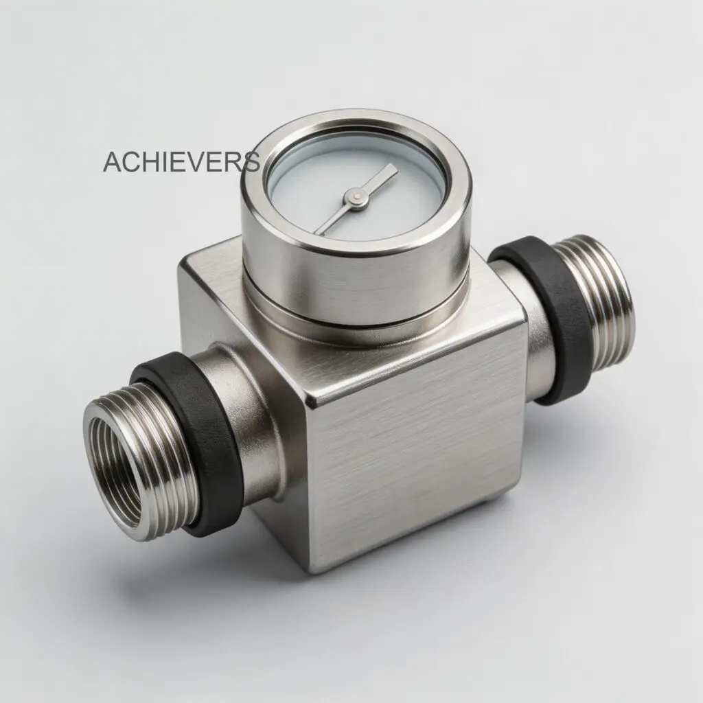
The mechanical rotation of the gears must then be translated into a readable output without compromising the pressure boundary of the meter body. High-performance Oil Flow Meters achieve this via magnetic coupling. High-strength permanent magnets embedded in the rotors trigger Hall-effect sensors or reed switches located outside the wetted pressure boundary. As the gears spin, the sensors register a discrete electrical pulse for every incremental volume displaced. These high-resolution pulses are transmitted to an electronic digital display, allowing for local totalization and integration into centralized PLC or SCADA architectures.
2. Complete Technical Specifications
Evaluating industrial oil flow meter specifications for manufacturers requires a deep understanding of the mechanical thresholds, material limits, and electronic communication capabilities of the device. The following data details the engineering specifications derived from the manufacturer’s technical data, outlining the robust parameters required for heavy industrial integration.
| Parameter | Specification | Engineering Notes & Applications |
| :— | :— | :— |
| Flow Rate Range | 1.0 LPH to 24,000 LPH | Exceptional turndown ratio capable of measuring both micro-dosing and bulk transfer. |
| Maximum Flow (In-line) | Up to 80 L/min (21 GPM) | Specific to in-line oval gear configurations for rapid fluid dispensing. |
| Line Size Connections | 6 mm to 150 mm (1/4" to 6") | Flanged or threaded configurations to match standard international piping infrastructure. |
| Measurement Accuracy | ±0.5% of reading | Ensures custody-transfer grade precision across the entire operating flow range. |
| Repeatability | ±0.1% to better than 0.02% | Critical for automated batching consistency and quality control in blending plants. |
| Max Operating Temp | Up to 150°C (302°F) | Safely handles high-temperature Furnace Oil and heated heavy base oils without rotor seizure. |
| Body Material | Lightweight Aluminum Alloys | Provides high tensile strength and pressure containment while minimizing skid weight. |
| Output Signals | Analog 4-20 mA & RS485 | Supports seamless integration into legacy DCS systems and modern Modbus RTU networks. |
| Calibration Method | Step-less calibration system | Allows for micro-adjustments in the field to eliminate K-factor drift over years of operation. |
| Display Interface | Electronic digital display | Rotatable register top (90º increments) for optimal viewing ergonomics in constrained pipe racks. |
| Filtration | Integrated mesh strainer | Protects tight gear-to-chamber clearances from particulate damage and wear. |
| Warranty | 1 year standard (up to 3 years) | Comprehensive support backed by guaranteed spare parts availability. |
The integration of dual electronic outputs (4-20 mA analog and Serial RS485 Modbus) transforms the flow meter from a simple mechanical totalizer into an intelligent node within a larger industrial network. The 4-20 mA loop provides real-time proportional flow rate data, immune to standard electromagnetic interference (EMI) found in heavy plant environments. Simultaneously, the RS485 Modbus RTU interface allows digital transmission of totalized volumes, diagnostic data, and instantaneous flow rates, ideal for complex automation architectures.
Furthermore, the physical construction utilizes compact aluminum alloy bodies. This metallurgical choice drastically reduces the total weight of the metering skid, allowing for easier overhead installations and reducing structural stress on piping networks, all while maintaining the burst pressure ratings required by API and ISO standards.
3. Performance Characteristics and Error Sources
Understanding oil flow meter accuracy vs viscosity and temperature is the most critical competency for an industrial instrumentation engineer. While positive displacement meters are exceptionally accurate, their real-world performance is governed by fluid dynamics—specifically, the concept of "slippage" or slip flow.
Slippage and Viscosity Dynamics
Slippage refers to the minute volume of fluid that escapes through the microscopic mechanical clearances between the gear teeth and the internal chamber walls without being actively measured. Because oval gear meters require a finite clearance to rotate without galling, this slip path always exists.
According to the Hagen-Poiseuille equation for flow through a restriction, the slip flow ($Q_{slip}$) is directly proportional to the differential pressure ($\Delta P$) and inversely proportional to the fluid's dynamic viscosity ($\mu$).
Therefore, as fluid viscosity increases (e.g., pumping heavy lube oils or base oils), the fluid resists shearing through these microscopic clearances, effectively sealing the gaps. This reduces slippage to near zero, driving the volumetric efficiency ($\eta_v$) toward 100%. Conversely, when measuring thin fluids like kerosene or hot diesel, slippage increases slightly. High-quality Oil Flow Meters compensate for this by offering multi-point step-less calibration, allowing engineers to program customized K-factors that flatten the accuracy curve for specific fluid viscosities.
Temperature Effects and Thermal Expansion
Temperature heavily dictates system accuracy through two distinct mechanisms: fluid viscosity alteration and metallic thermal expansion.
- Fluid Shift: As oil temperatures rise, their kinematic viscosity drops logarithmically. A heavy furnace oil pumped at 150°C behaves fluidically like diesel.
- Thermal Expansion: The aluminum alloy rotors and housing expand at elevated temperatures. If the temperature exceeds design specifications, the gears can expand faster than the housing, reducing clearances to zero and causing catastrophic mechanical seizure. Conversely, if the system is calibrated at 20°C and operated at 100°C, the expanded clearances may increase slippage. Modern industrial meters are engineered with specific thermal expansion tolerances to maintain ±0.5% accuracy even at extreme continuous operating temperatures of 150°C.
Air Entrainment and Pulsation
Positive displacement meters measure strictly by volume. They cannot differentiate between liquid oil and trapped air. If an upstream pump introduces air into the fluid line (two-phase flow), the meter will measure the air as liquid, leading to massive over-registration errors. To mitigate this, global installations mandate the use of upstream air eliminators and de-aeration tanks.
Additionally, pulsating flow from diaphragm or piston pumps can cause the oval gears to rapidly accelerate and decelerate, introducing inertia-based measurement errors. Proper dampening accumulators and the inherent low-pressure-drop design of the meter allow it to handle moderate pulsations in both gravity-fed and pump-driven in-line applications.
When integrating these metrics into automated systems, such as a Liquid Batching System, accounting for viscosity shifts and eliminating air entrainment ensures that the batch controller shuts off the control valve at the exact specified mass or volume, preventing costly chemical over-spills or off-spec product blends.
4. Materials and Chemical Compatibility
The long-term survivability of a flow meter is entirely dependent on the chemical and metallurgical compatibility between its wetted parts and the process fluid. Oil Flow Meters constructed with strong aluminum alloys provide excellent resistance to a broad spectrum of hydrocarbons, but seals and internal O-rings dictate the ultimate compatibility limit.
| Process Fluid | Compatibility | Engineering Notes on Performance & Sealing |
| :— | :— | :— |
| Hydraulic Oil | Excellent | Standard NBR or FKM seals suitable; high viscosity yields flawless ±0.5% accuracy. |
| Diesel Fuel | Excellent | Ideal for generator sets and fleet refueling; extremely stable calibration profile. |
| Furnace Oil (Up to 150°C) | Excellent | Requires high-temperature Viton/PTFE seals and specific thermal gear clearances. |
| Kerosene | Excellent | Lower viscosity increases baseline slip; requires specific calibration K-factor adjustment. |
| Heavy Base Oils | Excellent | High shear resistance virtually eliminates gear slippage; low pressure drop required. |
| Vegetable / Cooking Oils | Excellent | Used extensively in food processing; requires food-grade washdown maintenance protocols. |
| Lube Oils & Additives | Excellent | Maintains superior repeatability (0.02%) for critical automated blending plants. |
| Antifreeze / Coolants | Good | Compatible with aluminum body, but requires verification of specific elastomer seal compatibility. |
When selecting equipment, matching the seal material to the chemical composition of the oil is paramount. Nitrile (NBR) is standard for generic hydraulic and diesel applications. However, if the fluid contains high levels of aromatics or operates at extreme temperatures—such as 150°C furnace oil—fluorocarbon elastomers (FKM/Viton) or Polytetrafluoroethylene (PTFE) seals must be utilized to prevent seal swelling, extrusion, and subsequent fluid leakage.
For specific low-viscosity applications like high-speed automotive refueling, coupling the system with a dedicated Diesel Flow Meter ensures that the internal clearances are factory-optimized for the exact specific gravity and viscosity of standard diesel fuels.
5. Calibration, Verification, and Certification
Even the most precisely machined gears will experience minute wear over millions of rotations. To maintain custody-transfer accuracy and comply with strict international quality management systems (like ISO 9001 and OIML R 117), Oil Flow Meters must undergo rigorous factory calibration and periodic field verification.
When sourcing Oil Flow Meters in India for export-oriented skid packages, procurement heads must ensure that the manufacturer provides verifiable calibration certificates traceable to recognized metrology standards. The step-less calibration system integrated into these meters allows technicians to micro-adjust the registration output without replacing physical gear sets, ensuring accuracy remains consistent between calibration levels.
To execute a precise field verification and recalibration using a volumetric master prover, facility engineers should follow this strict procedure:
- System Purging and Stabilization: Circulate the specific process oil through the flow meter and the master prover for at least 15 minutes to equalize fluid temperatures and eliminate trapped air pockets from the piping geometry.
- Zeroing the Registers: Ensure that both the electronic digital display of the meter under test and the master prover (or calibrated weigh scale) are reset to absolute zero.
- Establishing Dynamic Flow: Open the downstream control valves to establish a stable, continuous flow rate that matches the nominal operating conditions of the plant (e.g., 5,000 LPH).
- Volumetric Dispensing: Dispense a statistically significant test volume of oil—typically no less than 100 times the internal swept volume of the flow meter—into the master prover to minimize start/stop volumetric uncertainties.
- Data Comparison and Deviation Calculation: Once flow is stopped, record the totalized volume on the meter's display and compare it directly to the certified volume captured by the prover. Calculate the percentage of error.
- Step-less Calibration Adjustment: Access the electronic control register via the digital interface or Modbus protocol and adjust the internal K-factor (pulses per liter) to mathematically negate the recorded volumetric deviation.
- Multi-Point Verification: Repeat the proving process at the minimum, nominal, and maximum flow rates (e.g., 1,000 LPH, 5,000 LPH, and 20,000 LPH) to verify the linearity and repeatability (better than 0.02%) across the full operational spectrum.
- Sealing and Documentation: Lock the calibration settings and attach physical tamper-evident seals to the register cover, logging the new K-factors and fluid temperatures into the facility's asset management software for audit compliance.
This rigorous attention to metrology guarantees that organizations looking to buy oil flow meters supplier equipment will experience transparent communication, zero hidden costs, and enduring support through accurate, verified data.
FAQ
Q: What is the maximum temperature an oval gear oil flow meter can handle?
A: High-performance models are engineered to handle continuous fluid temperatures up to 150°C (302°F). This is particularly necessary for measuring heavy, high-temperature Furnace Oil, requiring specialized high-temp seals and optimized internal gear clearances.
Q: Does fluid viscosity affect the accuracy of positive displacement meters?
A: Yes, but in a beneficial way. Higher viscosity fluids resist slipping through the internal gear clearances, thereby increasing the volumetric efficiency and accuracy. For very low viscosity fluids, the meter’s step-less calibration must be adjusted to account for increased slip flow.
Q: Do I need to install straight piping runs before the flow meter?
A: No. Unlike turbine or ultrasonic flow meters that require fully developed laminar flow profiles, positive displacement oval gear meters measure discrete volumes of fluid. They are completely unaffected by external piping constraints, elbows, or valves located immediately upstream or downstream.
Q: How often should industrial oil flow meters be recalibrated?
A: For custody transfer or critical chemical blending, recalibration is recommended every 12 months. However, in standard lubrication or fuel transfer applications, the durable aluminum alloy construction and robust gear design often allow for up to 24–36 months of stable operation before verification is required.
Q: Can these meters output data directly to my plant's DCS or PLC?
A: Yes. Modern units feature advanced electronic digital displays equipped with both analog 4-20 mA outputs and Serial RS485 MODBUS communication, allowing for real-time flow rate monitoring and totalization across sophisticated SCADA networks.
Q: What happens if solid particles enter the flow meter?
A: Oval gears operate with microscopic clearances. Solid particulates can jam the gears or severely score the chamber walls, destroying accuracy. To prevent this, these meters are provided with an integrated mesh strainer that must be maintained and cleaned regularly.
Q: Can this type of meter handle pulsating flow from a diaphragm pump?
A: While they can handle moderate pulsation due to their low pressure drop, severe hydraulic pulsation can cause inertia-based inaccuracies and premature bearing wear. It is highly recommended to install pulsation dampeners upstream when using aggressive positive displacement pumps.
Ready to optimize your plant's fluid measurement and automated batching processes? Contact our technical engineering team today to discuss your specific flow rate requirements, chemical compatibility needs, and site conditions, and let us custom-configure the ideal high-precision metering solution for your facility.
