


In the high-stakes environment of Indian industrial operations, fuel accountability is not just a metric—it is a critical control point for profitability. For plant managers, fleet operators, and procurement heads, diesel often represents one of the largest recurring operational expenses. Whether managing a captive power plant, a logistics fleet, or a manufacturing facility, the inability to accurately track every litre of fuel dispensed or transferred can lead to significant financial leakage through pilferage, inefficiencies, or simple measurement errors.
To combat this, reliable measurement instrumentation is essential. However, the market is flooded with various metering technologies, making the selection process complex. Choosing the wrong device can result in frequent maintenance, poor accuracy due to viscosity changes, or incompatibility with automation systems. As premier fuel flow meter suppliers in India, we understand that the solution lies in matching the specific engineering characteristics of the meter to the operational realities of the site.
This guide focuses on the technical nuances of the Fuel Flow Meter, specifically designed for the rigorous demands of diesel handling, petroleum transfer, and industrial fluid measurement. We will explore how to navigate the specifications—ranging from flow rates and viscosity to output signals—to ensure you deploy a system that delivers precision, durability, and verifiable data.
1. Understanding the Fuel Flow Meter Architecture
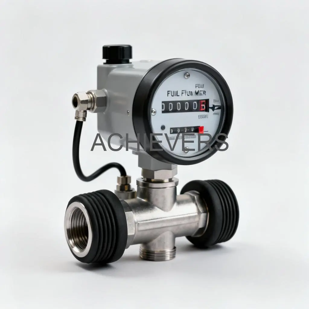
The Fuel Flow Meter by Chintan Engineers is not a single-design-fits-all product; rather, it is a category of precision instruments engineered for specific hydraulic conditions. These systems are designed to handle everything from light diesel and petrol to heavier lubricants, ensuring accountability across the fluid handling spectrum.
At a fundamental level, these meters utilize specific internal mechanisms—Turbine, Positive Displacement (PD), or Piston—to translate fluid movement into measurable volume. According to the technical specifications, the Fuel Flow Meter covers a vast flow spectrum, capable of measuring from as low as 5 L/h (ideal for low-consumption dosing) up to 1,300 L/min for high-volume bulk transfers.
Technical Specifications and Capabilities
The versatility of these meters is defined by their rugged construction and electronic flexibility:
- Meter Technologies: The lineup includes Turbine sensors (CE-210) for continuous flow, mechanical or digital Positive Displacement units (CE-110/111) for robust field use, high-accuracy PD meters (CE-113) for custody transfer, and precision Piston PD models (CE-212).
- Material Construction: Built for harsh Indian industrial environments, the bodies are constructed from Aluminium or Stainless Steel. Critical internal seals use Viton or Buna, ensuring chemical compatibility with diesel, petrol, biodiesel, and lubricants.
- Viscosity Handling: The systems are engineered to manage a wide viscosity window, ranging from 1 mm²/s (standard fuels) up to 10⁶ mm²/s for heavy fluids, depending on the specific model selected.
- Accuracy Standards: Standard models maintain a ±0.5% accuracy, while specialized transfer builds achieve a tighter ±0.2% tolerance, crucial for billing and custody transfer.
The integration potential is equally robust. These meters offer outputs ranging from simple mechanical registers for manual logging to LCD totalizers, pulse outputs, and 4–20 mA signals for integration with PLCs, preset controllers, and data loggers.
2. Selecting the Right Meter Technology for Industrial Operations
This blog will guide plant engineers, purchase heads, and fleet operators in India on how to select the most suitable Fuel Flow Meter based on flow rate, viscosity range, accuracy, and integration needs. It will compare turbine, piston, and positive displacement models with industrial scenarios like depot fueling, bulk transfers, and dispenser retrofits.
Selecting a diesel flow meter for industrial use requires analyzing the "Angle of Attack"—matching the internal measuring element to the fluid dynamics of your application.
Positive Displacement (PD) vs. Turbine vs. Piston
Different industrial scenarios demand specific measuring principles. Here is how the variants of the Fuel Flow Meter compare:
Scenario A: Depot Fueling and Truck Stops (The Workhorse)
For fleet operators managing internal fuel depots, ruggedness is paramount. The CE-110 Mechanical Flow Meter uses a positive displacement design.
- Why it fits: It operates independently of viscosity changes and requires no external power. The mechanical counter (with reset and cumulative totals) is ideal for drivers and operators to manually log fuel dispensed into trucks. It handles 20–300 L/min with ±0.5% accuracy, making it perfect for standard loading operations where digital integration isn't required.
Scenario B: Bulk Transfers and Custody Transfer (The Precision Instrument)
When fuel is being bought or sold, or transferred in large volumes between tanks, accuracy translates directly to currency. The CE-113 High Accuracy Transfer Meter is the positive displacement fuel flow meter of choice here.
- Why it fits: It supports high flow rates (25–1300 L/min) and achieves ±0.2% accuracy. Crucially, it includes an air eliminator and strainer—essential components to ensure you are measuring liquid, not air pockets, which is common during high-speed pumping. It can be paired with ticket printers to generate physical proof of the transaction.
Scenario C: Dispenser Retrofits and Batching (The Digital Solution)
For plants upgrading existing pumps to automated systems, the CE-111 Digital Flow Meter or CE-212 Piston PD Meter offers the necessary intelligence.
- Why it fits: The CE-111 offers a digital LCD readout and is pulse-ready for PLC connection. The CE-212, with its 4-piston assembly, offers micro-accuracy (±0.2%) at lower flow rates (5–60 L/min), making it ideal for precise batching systems where overdosing additives or fuel is unacceptable.
Scenario D: Continuous Monitoring and Process Control (The Sensor)
For integrating flow data into a SCADA system or monitoring generator consumption, the CE-210 Turbine/Helical Sensor is effective.
- Why it fits: With a compact footprint and 4–20 mA output, it handles wide viscosity swings and is pulsation tolerant. It is excellent for continuous data streaming regarding fuel lines or chemical dosing.
3. Configuration and Selection Guide
To source an accurate flow meter for petroleum applications, buyers must look beyond the pipe size. An incorrectly specified meter will either wear out prematurely or provide erratic data. When configuring a Fuel Flow Meter, consider the following technical criteria:
1. Fluid Viscosity and Temperature
Viscosity changes with temperature. A turbine meter that works well for hot diesel might lose accuracy if the fuel cools and thickens.
- Low Viscosity (Diesel/Kerosene): Turbine meters (CE-210) are cost-effective and accurate.
- Variable/High Viscosity (Lube Oil/Cold Diesel): Positive Displacement (Oval gear or Helical) meters are superior as they mechanically trap fixed volumes of fluid, making them immune to viscosity shifts.
2. Flow Rate Matching
Never size a meter solely by pipe diameter (e.g., "I need a 2-inch meter"). Size it by flow rate.
- Oversizing: Operating a meter below its minimum flow range (e.g., running a 1300 L/min meter at 10 L/min) results in "slippage," where fluid passes unmeasured.
- Undersizing: Running a meter constantly at its maximum rated capacity causes rapid wear of bearings and rotors.
- Recommendation: Select a Fuel Flow Meter model where your typical operating flow rate falls within 30% to 70% of the meter's maximum capacity.
3. Output and Signal Requirements
How will the data be used?
- Manual Logging: Choose the CE-110 with a mechanical register.
- Automation: If you have a batching PLC or a remote telemetry dashboard, specify the CE-111, CE-113, or CE-210 with Pulse or 4–20 mA outputs.
- Receipts: For proof of delivery, ensure the configuration includes a ticket printer (available with CE-113).
4. Accuracy and Compliance Requirements
- Internal Inventory: ±0.5% accuracy (Standard PD or Turbine) is usually sufficient.
- Custody Transfer/Billing: You must opt for ±0.2% accuracy models (CE-113 or CE-212) and ensure the unit is capable of being sealed and calibrated per Legal Metrology standards.
4. Typical Industrial Applications
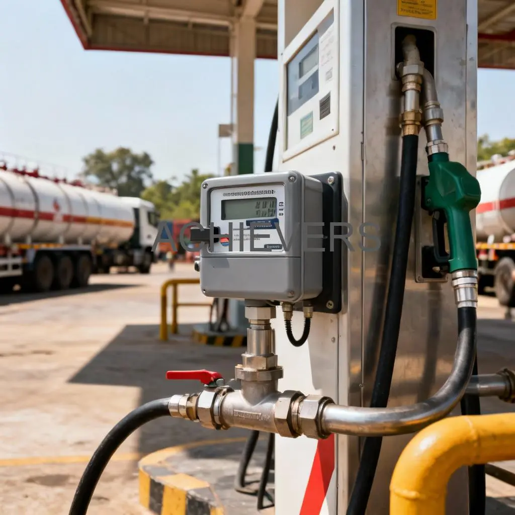
The Fuel Flow Meter is versatile, finding its place in various sectors across the Indian industrial landscape. Based on the product specifications, these are the primary applications:
- Bulk Loading Gantries: High-volume transfer of diesel from storage tanks to tanker trucks using the CE-113 for precise custody transfer and ticket printing.
- Mobile Bowsers and Refuelers: The CE-113 and CE-111 are often mounted on trolley frames or directly onto fuel trucks to measure delivery to heavy earthmovers and mining equipment.
- Manufacturing Plant Fuel Monitoring: Utilizing CE-210 turbine sensors to monitor fuel consumption in boilers, furnaces, and diesel generators (DG sets) to detect efficiency drops or theft.
- Chemical and Additive Dosing: The CE-212 piston meter’s high precision at low flow rates makes it ideal for injecting specific volumes of additives into fuel streams or batching chemicals.
- Dispenser Retrofits: Upgrading old mechanical dispensers with the CE-111 Digital Flow Meter to enable digital totalizing and integration with fuel management software.
5. Installation, Commissioning, and Service
Even the best fuel flow meter for diesel transfer will fail if installed incorrectly. Mechanical stress, air pockets, and electrical noise are common enemies of accurate measurement.
Best Practices for Installation
- Survey and Prep: Plan the piping orientation. Ensure straight runs of pipe before and after the meter (if required by the specific model) to stabilize flow.
- Filtration and Air Elimination: This is critical. Debris can jam rotors, and air can spin turbines, registering "phantom flow." Always install the recommended strainers and air eliminators, particularly for bulk transfer applications like the CE-113.
- Orientation: Mount the meter in the recommended orientation (horizontal or vertical) to ensure the rotors are supported correctly and air does not get trapped in the measuring chamber.
- Wiring: For digital models, use shielded cables for Pulse or 4–20 mA outputs to prevent electrical interference from pumps or motors.
Calibration and Maintenance
To maintain the stated accuracy of ±0.5% or ±0.2%, rigorous "proving" is necessary.
- Initial Proving: Run a "prover can" or master meter test immediately after installation to establish a baseline.
- Adjustment: Adjust the calibration wheel (mechanical) or K-factor (digital) until the meter matches the proven volume.
- Routine Verification: We recommend annual calibration intervals, or as dictated by Legal Metrology for custody applications.
- Support: As established manufacturers, we provide end-to-end support, including AMC services, ensuring that genuine spares and technical expertise are available to keep your Fuel Flow Meter operational for years.
Summary
Selecting the right flow metering technology is a balance of fluid physics, operational requirements, and data integration needs. Whether you require a robust mechanical counter for a remote mining depot or a high-precision digital system for a manufacturing plant, the Fuel Flow Meter offers a configuration to match.
By focusing on the specific viscosity, flow rate, and accuracy requirements of your site, you can eliminate guesswork and secure your fuel assets against loss.
Ready to configure your system?
To ensure you receive the correct specification, please contact our engineering team with the following details:
- Fluid name and approximate viscosity.
- Minimum and maximum flow rates.
- Output requirements (Mechanical, Pulse, 4–20mA).
- Application type (e.g., Unloading, Dispensing, Dosing).
Contact us here: https://chintanengineers.in/products/fuel-flow-meter/
