


A 1% calibration drift on a 5,000 L/day diesel throughput costs your operation exactly ₹1.35 lakh per month in untracked fuel. I have walked into hundreds of plants across GIDC industrial estates in Gujarat where plant managers blame the flow meter for this massive discrepancy. Nine times out of ten, the meter is perfectly fine. The installation is the true culprit.
As a flow measurement engineer with 22 years of field experience at Chintan Engineers, I can tell you that buying a high-accuracy instrument and plumbing it poorly is the most common mistake in Indian industry. Think your brand-new meter will magically read ±0.5% out of the box? Think again. Whether you are setting up a differential fuel monitor for a 1000 kVA genset or commissioning a bulk diesel unloading gantry, fluid dynamics do not care about your budget constraints or your project timelines.
When a meter leaves our calibration rig, it operates under strictly controlled temperatures with perfectly conditioned, air-free fluid. Your factory floor, however, is not a calibration lab.
This is my direct, data-backed breakdown on industrial flow meter commissioning, specifically tailored to the heat, dust, and electrical realities of Indian manufacturing. I will explain exactly how to install, protect, and calibrate your systems so that every drop of fuel is accounted for.
In This Article
- The Physics of Poor Installation: Why Good Meters Fail
- Diesel Flow Meter Piping Layout: Straight Run Requirements
- Air Elimination and Strainer Positioning
- Differential Measurement: Diesel Generator Fuel Monitoring
- Shielding Against Extreme Heat and Dust in Indian Factories
- Selecting the Right Fuel Flow Meter Technology
- Step-by-Step Industrial Flow Meter Commissioning
- Frequently Asked Questions
- The Bottom Line
The Physics of Poor Installation: Why Good Meters Fail
When you pump diesel from an underground storage tank to a day tank, you introduce three volatile variables into the piping system: entrained air, piping-induced turbulence, and particulate matter. A fuel flow meter installation that ignores these variables will fail, regardless of the precision technology housed inside the casing. (Trust me, nothing hurts your bottom line faster than paying for a pocket of vapor.)
Many procurement managers assume that a meter with a stated accuracy of ±0.5% will automatically deliver that accuracy once bolted into the pipeline. This is a fundamental misunderstanding of fluid mechanics. Accuracy is a system-level outcome, not just an instrument specification. If the fluid arriving at the meter's inlet is contaminated with vapor pockets or disrupted by asymmetric velocity profiles, the volumetric readout will be heavily compromised.
Diesel Flow Meter Piping Layout: Straight Run Requirements
The requirement for straight pipe runs depends entirely on your chosen measurement technology. I've calibrated enough turbine meters to know they don't belong anywhere near turbulent fluid flow, and I'll explain exactly why.
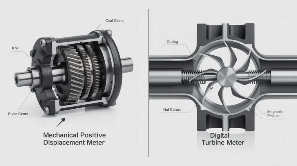
Turbine Flow Meters (CE-210)
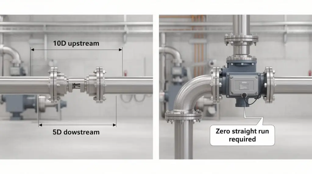
Turbine and helical rotors rely on fluid velocity to calculate volume. The kinetic energy of the passing fluid rotates the blades, and a magnetic pickup coil counts the blade passes. If the fluid enters the metering chamber spinning, swirling, or skewed due to a recent elbow joint, the rotor will spin artificially fast or slow.
For a turbine meter, you absolutely must provide a straight, unobstructed pipe run of 10 pipe diameters (10D) upstream and 5 pipe diameters (5D) downstream.
If you install a 2-inch turbine meter directly after a 90-degree elbow or a partially open butterfly valve, expect a permanent +2% to +4% reading error.
Positive Displacement Meters (CE-110, CE-113, CE-212)
Positive displacement (PD) meters—whether oval gear, rotary vane, or piston type—operate on a completely different principle. They measure discrete volumetric parcels. They act essentially as hydraulic motors, passing an exact volume of fluid with each rotation. Because they capture fluid in sealed chambers, they do not care about the velocity profile or swirl.
A positive displacement meter setup requires zero straight run. You can bolt a 90-degree elbow directly to the inlet flange, and it will not affect the ±0.5% (or ±0.2% for the CE-113) accuracy. This makes PD meters exceptionally valuable in compact plant rooms or mobile truck skids where straight piping is physically impossible.
For a closer look at how viscosity and fluid dynamics impact meter choice, I strongly suggest reviewing our technical breakdown in Decoding Oil Flow Meter Specs: An Engineer's Guide.
Air Elimination and Strainer Positioning
If you take only one piece of advice from my two decades in the field, let it be this: Meters measure volume, not state. If you push a mixture of 95% diesel and 5% air through a volumetric meter, the meter will happily charge you for 100% liquid.
The Custody Transfer Mandate
When unloading tankers at a depot, the final few hundred liters always pull air into the pump suction as the tank runs dry. Furthermore, cavitation in the pump can release dissolved gases from the fuel.
You can't argue with physics, and you certainly can't argue with the Weights and Measures inspector. OIML R117 guidelines and the Indian Legal Metrology Act mandate the use of an air eliminator for any custody transfer application. For bulk loading gantries, you must install an air eliminator upstream of the meter, positioned at the highest point in the pipework. This allows trapped air and vapor to vent out before reaching the measuring chamber.
Warning: Skipping the air eliminator on a bulk unloading line is financial sabotage. You will end up paying for compressed air instead of diesel when the supplier's tanker inevitably runs dry.
Precision Strainer Selection
Machined clearances inside a high-accuracy transfer meter (like our CE-113) are measured in fractions of a millimeter. A single piece of welding slag from your newly installed piping will jam the oval gears or pistons instantly.
- Diesel & Kerosene: Use a minimum 60-mesh (250-micron) strainer.
- Heavy Fuel Oil (HFO) / LDO: Use a 40-mesh (400-micron) strainer to prevent unacceptable pressure drops, as these fluids have much higher viscosities.
- Placement: The strainer must be installed directly upstream of the air eliminator and flow meter.
Pro Tip: I never install a turbine meter without a minimum 40-mesh strainer upstream. For oval gear or piston PD meters handling diesel, I step that up to a 60-mesh minimum to protect the rotor clearances from abrasive rust scale originating in old underground storage tanks.
Losing fuel during bulk tanker unloading?
Our CE-113 Custody Transfer Meters come pre-configured with integrated air eliminators and high-capacity strainers to guarantee ±0.2% accountability.
Differential Measurement: Diesel Generator Fuel Monitoring
One of the most complex installations in an Indian factory is fuel monitoring for large backup Diesel Generator (DG) sets. Tracking fuel on a heavy-duty Cummins or Caterpillar engine is notoriously difficult because modern engines do not consume all the fuel they pull. They use excess diesel to cool the fuel injectors, returning hot, unburnt fuel back to the day tank.
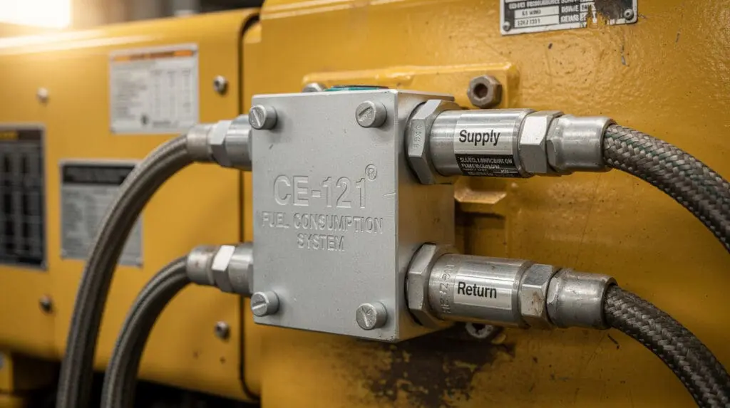
You cannot simply slap a standard meter on the supply line and call it a day. Instead, you need a differential measurement system like our CE-121 Fuel Consumption System.
The Thermal Expansion Trap
Ever wonder why your DG set might show negative consumption at idle? This is where many plant engineers fail: Return fuel is significantly hotter than supply fuel.
Diesel expands by approximately 0.083% per degree Celsius. If 100 liters of cold diesel (at 30°C) is supplied to the engine, and 80 liters of hot diesel (at 70°C) is returned, that 80 liters takes up more physical volume due to thermal expansion. If you use standard mechanical meters to manually subtract the return from the supply, your net consumption numbers will be wildly inaccurate.
The CE-121 utilizes two separate positive displacement flow sensors (one for supply, one for return) and processes the differential in a central digital LCD unit, which can output data via RS485 Modbus. For absolute precision, the system must account for these temperature differentials. The sensors are built from anodized aluminum to withstand the high temperatures and severe vibrations of engine-block mounting.
Shielding Against Extreme Heat and Dust in Indian Factories
Indian industrial conditions are brutal on sensitive instrumentation. A typical installation in a cement plant in Rajasthan will see ambient temperatures of 48°C and heavy, abrasive dust loading. A chemical plant in Dahej will experience corrosive, 95% humidity during the monsoon season.
- Thermal Expansion & Sunshades: Direct sunlight on a localized section of piping will cause the fuel inside to expand, altering volumetric readings. (I once saw an entire batching system drift 3% simply because the afternoon sun hit an uninsulated section of overhead piping.) Install flow meters close to the dispensing point, and always provide a physical sunshade. For extreme custody accuracy, utilize flow computers that apply API volume correction based on real-time RTD temperature inputs.
- Dust Ingress & IP Ratings: In dusty environments like mining depots, avoid mechanical registers with exposed reset knobs if possible. Fine silica dust grinds down the rotating number wheels over time. Instead, opt for a digital meter like the CE-111 with an IP65/IP67 rated enclosure and a robust LCD display.
- Electrical Isolation: Voltage fluctuations in rural industrial grids regularly destroy sensitive pulse transmitters and Hall effect sensors. Ensure your PLC or remote monitoring kit uses a regulated 24VDC SMPS. More importantly, the system must be properly earth-grounded to prevent ground loops from interfering with the 4–20 mA or pulse signals. I have seen hundreds of erratic pulse readings cured simply by terminating the cable shield at the PLC ground.
Selecting the Right Fuel Flow Meter Technology
Before you run a single drop of fluid, you must specify the correct hardware. Installing a delicate turbine meter on a high-viscosity furnace oil line is a recipe for a jammed rotor. Here is how our primary fuel flow meters stack up based on hard field realities.
| Model | Technology | Flow Range | Accuracy | Best For Indian Field Conditions |
| :— | :— | :— | :— | :— |
| CE-110 | Mechanical PD | 20 – 300 L/min | ±0.5% | Dusty fleet depots without stable power; true rugged mechanical tracking without electrical dependencies. |
| CE-111 | Digital PD | 20 – 300 L/min | ±0.5% | Dispenser skids needing battery-backed digital readouts and pulse outputs for PLC integration. |
| CE-113 | High-Accuracy PD | 25 – 1300 L/min | ±0.2% | Bulk loading gantries requiring custody transfer accuracy, ticket printing, and BIS compliance. |
| CE-210 | Turbine/Helical | 5 – 10,000 L/h | ±0.5% – 1% | Clean, low-viscosity fuels requiring a compact footprint and remote flow monitoring in process lines. |
| CE-212 | Piston PD | 5 – 60 L/min | ±0.2% | Micro-accurate fuel dispensers and localized diesel generator consumption tracking. |
TCO Example: Upgrading for Custody Transfer
Plant managers often balk at the higher initial capital cost of a ±0.2% high-accuracy transfer meter (CE-113) compared to a standard ±0.5% digital meter (CE-111).
Run the numbers on Total Cost of Ownership (TCO) and the choice becomes obvious.
On a 10,000 L/day depot line, an improvement of just 0.3% in accuracy captures 30 liters of previously unrecorded fuel daily. At ₹90/liter, you save ₹2,700 per day.
The premium cost of the precision custody-transfer meter is completely recovered in less than two months of continuous operation. After that 60-day mark, that ₹2,700 per day is pure bottom-line savings.
Pro Tip: If you are building an automated batching system, remember that the flow meter is only as accurate as the valve closing behind it. Match a high-speed pulse output meter with a fast-acting dual-stage solenoid valve to eliminate fluid overrun. You can read more about this in our Engineer's Guide: Liquid Batching Systems.
Step-by-Step Industrial Flow Meter Commissioning
Once the hardware is bolted onto the line, the commissioning phase dictates the long-term reliability of your measurement data. Do not rush this process.
- System Flushing (Crucial): Never flush a newly installed piping system through the flow meter. Weld slag, thread tape fragments, and pipe rust will destroy the machined internals. Install a spool piece (a temporary blank pipe) in place of the meter. Flush the lines at maximum pump velocity for at least 30 minutes, clean the strainer basket completely, and then install the flow meter.
- Mechanical Fitment: Ensure pipe flanges are perfectly aligned. Bolting down a misaligned flange introduces massive mechanical stress on the metering chamber. This stress can warp the aluminum or stainless casing by mere fractions of a millimeter—which is enough to bind the tightly-toleranced rotors in a positive displacement meter.
- Electrical Termination: For digital output models providing pulse or 4-20mA signals to a SCADA system, strictly use shielded twisted-pair cables. Terminate the shield at the PLC ground only, leaving the meter end floating. This prevents ground loops from artificially inflating your pulse counts.
- Proving and Calibration: Run a master meter test or use a Legal Metrology certified volumetric prover can (typically a 50L or 100L capacity). Run at least three full batches at your normal operating flow rate. Adjust the calibration wheel mechanism (for mechanical meters like the CE-110) or modify the K-factor in the digital electronics until the error is within the specified ±0.5% or ±0.2% tolerance. Do not calibrate at a trickle if you normally dispense at full pump speed.
- Compliance Sealing: Once calibrated, apply a lead wire seal to the calibration mechanism. This prevents unauthorized tampering by operators or fuel suppliers.
Need reliable real-time data for your ERP system?
Integrate our pulse-ready CE-111 or CE-210 meters with your existing PLC or telemetry dashboards for instant, remote fuel accountability.
Frequently Asked Questions
Does the orientation of the meter matter during installation?
Orientation matters immensely. Most positive displacement meters, particularly those with oval gears, should be mounted with the rotor shafts in a horizontal plane. Mounting them vertically places the entire weight of the rotors on the bottom thrust bearing, increasing mechanical wear and severely degrading low-flow accuracy over time. Always verify the orientation in the specific installation manual.
Why is my flow meter reading higher than the actual volume dispensed?
This is almost exclusively due to entrained air passing through the meter. Without an upstream air eliminator, the volumetric chamber measures air pockets as liquid volume, artificially inflating the totalizer reading. Another potential cause is electrical noise generating phantom pulses on your PLC input line, or a K-factor that was incorrectly calculated during commissioning.
Can I use a bypass line around the flow meter?
You can, and it is highly recommended for maintenance purposes (a block-and-bypass manifold configuration). However, the bypass valve must be a high-quality, zero-leakage isolation valve. Crucially, it must be physically padlocked or sealed shut during normal operations to prevent intentional fuel theft.
How often should fuel flow meters be recalibrated in Indian conditions?
In heavy industrial environments subject to high vibration and dust, I recommend verifying calibration every 6 months using a known prover. For custody transfer applications involving financial transactions, annual stamping and calibration by local Weights and Measures authorities is legally mandated under the Indian Legal Metrology Act.
Do these flow meters handle biodiesel or blended fuels?
Yes, our PD and Turbine meters handle biodiesel blends without issue. However, you must specify this requirement during procurement so our engineering team can equip the meter with Viton or Teflon seals instead of standard Buna-N. Standard Buna-N (Nitrile) rubber can swell and degrade when continuously exposed to high-percentage biodiesel blends (B20 and above).
What is a K-factor and how do I calculate it?
The K-factor is the number of electronic pulses a meter generates per unit of volume (e.g., 100 pulses per liter). If your prover can shows exactly 100 Liters, but your PLC only counted 9,800 pulses, your current K-factor is off. You calculate the new K-factor by dividing the actual pulses received by the actual proven volume.
The Bottom Line
Fuel is often the top operational expense in an Indian manufacturing facility, second only to raw materials. Treating flow meters as simple "plumbing fittings" rather than high-precision laboratory instruments is a mistake that costs Indian factories lakhs of rupees annually in untracked inventory.
Based on 22 years of field experience, here is my final recommendation for your operation:
If you are upgrading your depot or running a batching skid, do not install a meter without an upstream strainer and an air eliminator. If you require absolute, undeniable accountability for bulk transfers, deploy the CE-113 High Accuracy Transfer Meter with its ±0.2% custody-level accuracy and integrated air removal system.
For remote gensets, DG differential monitoring, or truck fueling where power is erratic or unavailable, the rugged CE-110 Mechanical Flow Meter remains the most fail-safe, reliable option in the Indian market.
Stop guessing your fuel consumption. Stop arguing with your fuel suppliers. Install it right the first time, protect the instrument from the elements, and let the data speak for itself.
Ready to audit your fuel measurement setup?
Contact our senior engineering team for a piping and flow study, or browse our complete range of precision fuel flow meters engineered for Indian conditions.
